Vector Displays
|
|
|
|
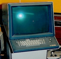
CRTs were embraced as output devices very early in the development of digital computers.
There close cousins, vacuum tubes, were some of the first
switching elements used to build computers. Today, the CRT is a the last remaining
vacuum tube in most systems (Even the flashing lights are solid-state LEDs).
Most likely, oscilloscopes were some of the first computer graphics displays.
The results of computations could be used to directly drive the vertical and
horizontal displacement plates in order to draw lines on the CRT's face. By
varying the current to the heating filament the output of the electron beam
could also be controlled. This allowed the intensity of the lines to vary from
bright to completely dark.
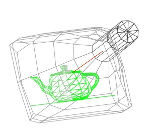
These early CRT displays were called vector, calligraphic or affectionately
stroker displays. The demonstration above gives some feel for how they worked.
By the way, this demo is an active Java applet. You can click and drag your
mouse inside of the image to reorient the CRT for a better view. Notice the
wireframe nature of the displayed image. This demo is complicated by the fact
that it's a wireframe simulation of a wireframe display system. Notice how the
color of the gray lines of the CRT vary from dark to light indicating which
parts of the model that are closer to the viewer. This technique is called depth-cueing,
and it was used frequently on vector displays.
The intensity variations seen on the teapot, however, are for a different reason.
Eventually, the phosphors recover from their excited state and the displaced
electrons return back to their original bands. The glow of the phosphor fades.
Thus, the image on the CRT's face must be constantly redrawn, refreshed, or
updated. The two primary problems with vector displays are that they required
constant updates to avoid fading, thus limiting the drawn scene's complexity,
and they only drew wireframes.