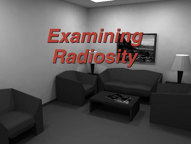
This slide set will explain the radiosity method for computer image generation and how the basic algorithm has been extended.
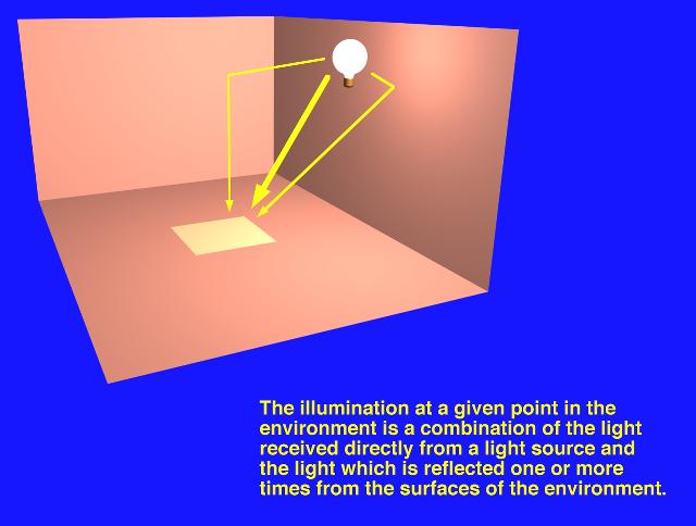
Every surface in an environment is illuminated by a combination of direct light and reflected light. The direct light is light energy which comes directly from a light source or light sources, attenuated only by some participating media (smoke, fog, dust). The reflected light is light energy which, after being emitted from a light source or light sources, is reflected off of one or more surfaces of the environment.
When light energy is reflected from a surface it is attenuated by the reflectivity of the surface, as some of the light energy may be absorbed by the surface, and some may pass through the surface. The reflectivity of a surface is often defined as its color.
Three images are displayed on this slide, illustrating several facets of computer image generation.
The image in the upper right corner was rendered with a scanline rendering algorithm, where the ambient component of light is approximated with a constant value. This results in even shading, even in areas where shadows or less illumination would be expected. No shadows are calculated.
The image in the middle and the image in the lower left corner were both rendered with a ray tracing global illumination algorithm. The image in the middle exhibits some of the characteristics of a typical ray tracing algorithm: mirror-like reflections and no ambient light component. Notice the hard-edged shadows cast by the light source. The image in the lower left corner retains the mirror-like reflection typical of a ray tracing algorithm, and adds an accurate ambient component of light, by allowing the rereflection of light energy through the environment, as well as soft shadows.

If a surface is defined to be a "diffuse reflector" of light energy, any light energy which strikes the surface will be reflected in all directions, dependent only on the angle between the surface's normal and the incoming light vector. This relationship is known as Lambert's law.
Light which is reflected from a surface is attenuated by the reflectivity of the surface, which is closely associated with the color of the surface. The reflected light energy often is colored, to some small extent, by the color of the surface from which it was reflected.
This reflection of light energy in an environment produces a phenomenon known as "color bleeding," where a brightly colored surface's color will "bleed" onto adjacent surfaces. The image in this slide illustrates this phenomenon, as both the red and blue walls "bleed" their color onto the white walls, ceiling and floor.

The "radiosity" method of computer image generation has its basis in the field of thermal heat transfer. Heat transfer theory describes radiation as the transfer of energy from a surface when that surface has been thermally excited. This encompasses both surfaces which are basic emitters of energy, as with light sources, and surfaces which receive energy from other surfaces and thus have energy to transfer.
This "thermal radiation" theory can be used to describe the transfer of many kinds of energy between surfaces, including light energy.
As in thermal heat transfer, the basic radiosity method for computer image generation makes the assumption that surfaces are diffuse emitters and reflectors of energy, emitting and reflecting energy uniformly over their entire area. It also assumes that an equilibrium solution can be reached; that all of the energy in an environment is accounted for, through absorption and reflection.
It should be noted the the basic radiosity method is viewpoint independent: the solution will be the same regardless of the viewpoint of the image.

The "radiosity equation" describes the amount of energy which can be emitted from a surface, as the sum of the energy inherent in the surface (a light source, for example) and the energy which strikes the surface, being emitted from some other surface.
The energy which leaves a surface (surface "j") and strikes another surface (surface "i") is attenuated by two factors:

[ OverView Part 1 UP ] [ OverView Part 2 ]
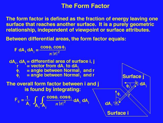
The "form factor" describes the fraction of energy which leaves one surface and arrives at a second surface. It takes into account the distance between the surfaces, computed as the distance between the center of each of the surfaces, and their orientation in space relative to each other, computed as the angle between each surface's normal vector and a vector drawn from the center of one surface to the center of the other surface. It is a dimensionless quantity.
The form factor, as initially shown, describes the form factor between two differential areas; that is, a point-to-point form factor. To use this form factor with surfaces which have a positive area, the equation must be integrated over one or both surface areas. The form factor between a point on one surface and another surface with positive area can be used if the assumption is made that the single point is representative of all of the points on the surface.
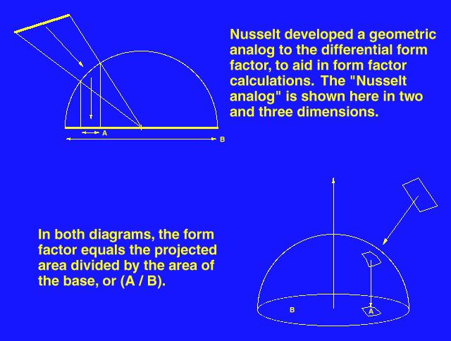
Differentiation of the basic form factor equation is difficult even for simple surfaces. Nusselt developed a geometric analog which allows the simple and accurate calculation of the form factor between a surface and a point on a second surface.
The "Nusselt analog" involves placing a hemispherical projection body, with unit radius, at a point on a surface. The second surface is spherically projected onto the projection body, then cylindrically projected onto the base of the hemisphere. The form factor is, then, the area projected on the base of the hemisphere divided by the area of the base of the hemisphere.
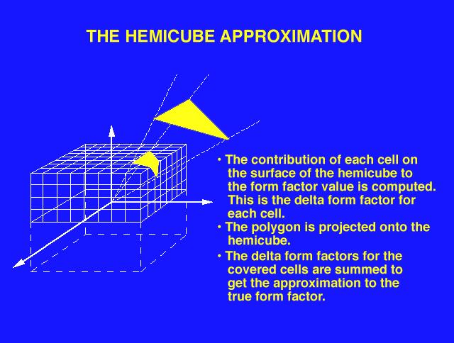
The "hemicube" form factor calculation method involves placing the center of a cube at a point on a surface, and using the upper half of the cube (the "hemicube" which is visible above the surface) as a projection body as defined by the "Nusselt analog."
Each face of the hemicube is subdivided into a set of small, usually square ("discrete") areas, each of which has a pre-computed form factor value. When a surface is projected onto the hemicube, the sum of the form factor values of the discrete areas of the hemicube faces which are covered by the projection of the surface is the form factor between the point on the first surface (about which the cube is placed) and the second surface (the one which was projected).
The speed and accuracy of this method of form factor calculation can be affected by changing the size and number of discrete areas on the faces of the hemicube.
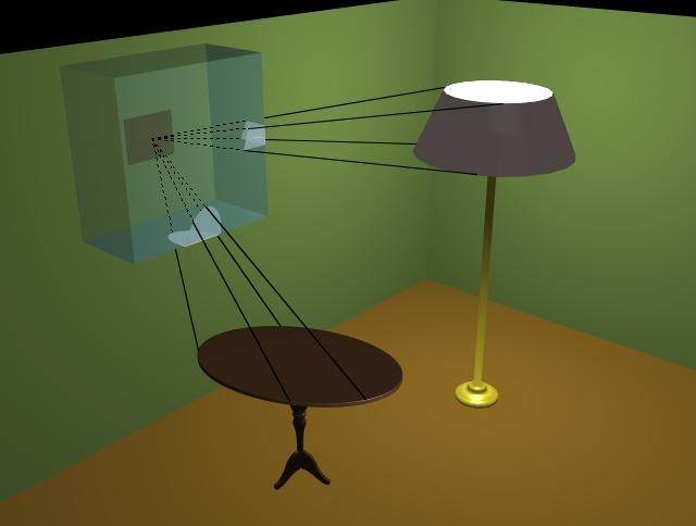
This illustration demonstrates the calculation of form factors between a particular surface on the wall of a room and several surfaces of objects in the room.
A standard radiosity image generation algorithm will compute the form factors from a point on a surface to all other surfaces, by projecting all other surfaces onto the hemicube and storing, at each discrete area, the identifying index of the surface that is closest to the point. When all surfaces have been projected onto the hemicube, the discrete areas contain the indices of the surfaces which are ultimately visible to the point. From there the form factors between the point and the surfaces are calculated.
For greater accuracy, a large surface would typically be broken into a set of small surfaces before any form factor calculation is performed.
Two classes of radiosity algorithms have been developed which will calculate the energy equilibrium solution in an environment.
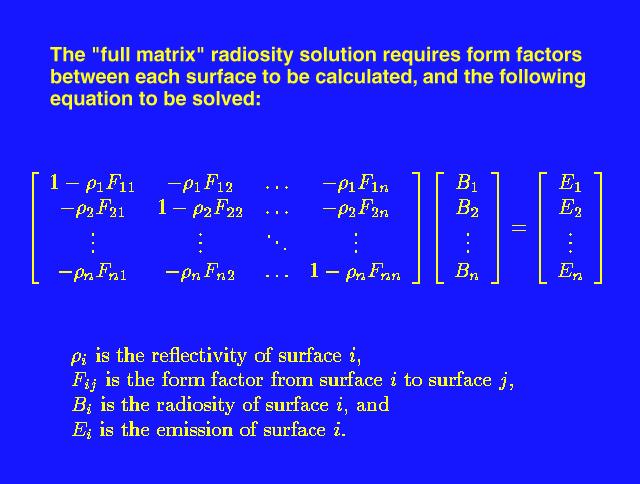
The "full matrix" radiosity solution calculates the form factors between each pair of surfaces in the environment, then forms a series of simultaneous linear equations, as shown in the upper figure. This matrix equation is solved for the "B" values, which can be used as the final intensity (or color) value of each surface.
This method produces a complete solution, at the substantial cost of first calculating form factors between each pair of surfaces and then the solution of the matrix equation. Each of these steps can be quite expensive if the number of surfaces is large: complex environments typically have upwards of ten thousand surfaces, and environments with one million surfaces are not uncommon. This leads to substantial costs not only in computation time but in storage.
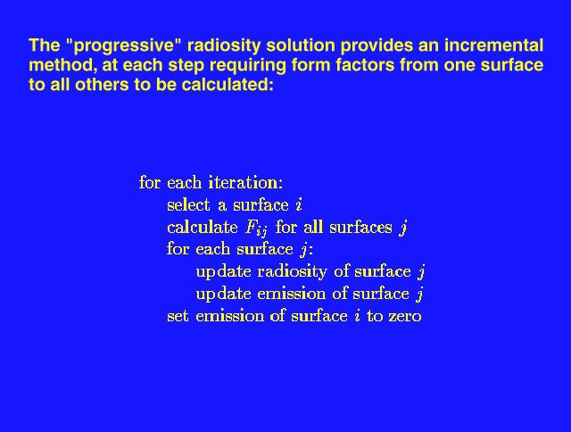
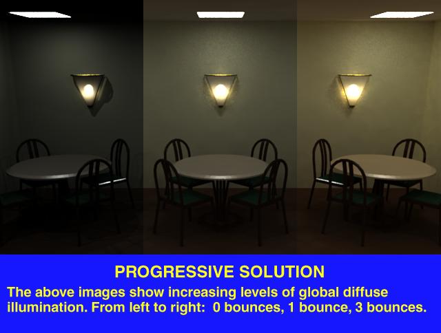
The "progressive" radiosity solution is an incremental method, yielding intermediate results at much lower computation and storage costs. Each iteration of the algorithm requires the calculation of form factors between a point on a single surface and all other surfaces, rather than all N-squared form factors (where "N" is the number of surfaces in the environment). After the form factor calculation, radiosity values for the surfaces of the environment are updated.
This method will eventually produce the same complete solution as the "full matrix" method, though, unlike the "full matrix" method, it will also produce intermediate results, each more accurate than the last. It can be halted when the desired approximation is reached. It also exacts no large (again, N-squared) storage cost.
This slide illustrates the iterative nature of the progressive method. The composite image shows that as the number of iterations increase, the accuracy of the intensity solution (and, hence, the resulting image) also increases. Of particular interest is the contribution of the color of the walls of the room to the overall color of the room in the right-most section of the composite image.
This image was created by calculating three separate but images, each halted at a different stage of rendering, and composited together afterwards.
[ OverView Part 1 ] [ OverView Part 2 UP ][ OverView Part 3 ]
Several variations on the basic progressive radiosity algorithm have been developed, in an effort to find the optimal method for producing the most pleasing results with minimum cost. Each variant calculates the form factors from a point on one surface to all other surfaces.
The "gathering" variant collects light energy from all other surfaces in the environment, attenuated by the calculated form factors, and updates the "base" surface. In this variant, as well as the "shooting" variant, the "base" surface is arbitrarily chosen.
The "shooting" variant distributes light energy from the "base" surface to all other surfaces in the environment, attenuated by the calculated form factors.
The "shooting and sorting" variant first calculates the surface with the greatest amount of unshot light energy, then uses this surface as the "base" surface in the "shooting" variant.
In addition to these, an initial "ambient" term can be approximated for the environment and adjusted at each iteration, gradually replaced by the true ambient contribution to the rendered image.
The "shooting and sorting" method is the most desirable, as it finds the surface with the greatest potential contribution to the intensity solution and updates all other surfaces in the environment with its energy.

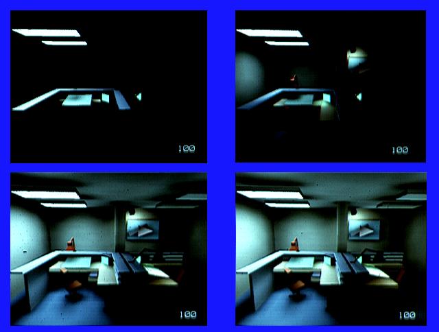
This slide shows four variations on the basic progressive radiosity algorithm, each halted after one hundred iterations. The upper left image is the "gathering" variant, the upper right image the "shooting" variant, the lower left image the "shooting and sorting" variant, and the lower right image is the "shooting and sorting and ambient" progressive radiosity variant.
The "shooting" variants show their superiority over the "gathering" variant here, as more of the scene is illuminated by them earlier. The "shooting and sorting" variant's concentration on those surfaces which contribute most to the overall solution is also shown.
Several important variations on the basic diffuse radiosity solution have been developed. The first is designed to relax the restriction on the diffuse-only nature of the basic radiosity solution, by breaking the intensity solution into two steps: first, a pass with a traditional radiosity algorithm to calculate the diffuse intensity of the surfaces, followed by a pass with a ray tracing algorithm, which collects the diffuse intensity information from the surfaces and adds to it specular information. This second pass is viewpoint- dependent: specular highlights on a surface are dependent on the location of both the light and the viewer relative to the surface.

Another variation on the basic diffuse radiosity solution adds the contribution of light passing through a participating medium, such as smoke, fog, or water vapor in the air.
In this algorithm, light energy is sent through a three-dimensional volume representing a participating medium, which both attenuates the light energy and, potentially, adds to the intensity solution through illumination of the participating medium.

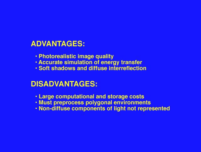
The largest single advantage of the radiosity method for computer image generation is the highly realistic quality of the resulting images. No other method accurately calculates the diffuse interreflection of light energy in an environment. Soft shadows and color bleeding are natural by-products of this method, just as hard shadows and mirror-like reflections are natural by-products of a typical ray-tracing algorithm.
In addition to being visually pleasing, the method can be quite accurate in its treatment of energy transport between surfaces.
The viewpoint independence of the basic radiosity algorithm provides the opportunity for interactive "walkthroughs" of environments, as one intensity solution for an environment will serve as the base for any particular view of the environment.
The costs associated with the radiosity method are substantial. The "full matrix" radiosity method requires a large amount of storage and long computation times for form factor calculation and matrix solution. The "progressive" method must also calculate a large number of form factors, many more than once.
Accuracy in the resulting intensity solution requires preprocessing the environment, subdividing large surfaces into a set of smaller surfaces, and more surfaces means more storage and computation.
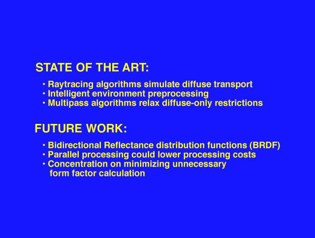
More recently, several new algorithms have been developed which help to alleviate the restrictions of the basic radiosity solution.
Ray tracing algorithms can be modified to handle the intricacies of accurate light transport between surfaces without explicit form factor calculation.
"Intelligent" pre-processing of environments can subdivide the surfaces of an environment based on the geometry of the environment and on the probable location of light-shadow boundaries, creating an optimal subdivision.
As noted previously, the inherent diffuse nature of the basic radiosity algorithm has been relaxed with the development of multiple pass algorithms which incorporate both the diffuse and specular components of light.
Current research efforts include more accurate modeling of the characteristics of lights and surfaces, through BRDFs (bidirectional reflectance distribution functions), concentration on minimizing the cost of form factor calculation, and increasing the accuracy of form factor calculation.
This image suggests one treatment of a consolation room in a hospital or physician's office. It is part of a research experiment comparing the effect of different lighting on the overall appearance and perception of an environment.

[ OverView Part 2 ] [ OverView Part 3 UP ] [ OverView Part 4 ]
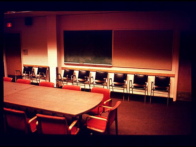
This image shows a typical conference room.

For comparison, this image is an actual photograph of the conference room modeled and rendered in the previous slide.
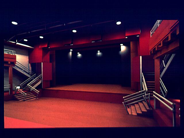
This image shows a model of a proposed theater near Candlestick Park in San Francisco, and contains 1,061,543 surface elements.
This image is the same model of the proposed theater used in the previous slide, but with the surface element mesh visible.

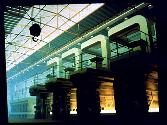
This image of a steel rolling mill was created using progressive radiosity. The original model contains about 30,000 polygons, which were subdivided into about 55,000 elements during the solution. It was computed on a DEC VAX 8700 and displayed using a Hewlett-Packard SRX graphics device.
This view of Le Corbusier's Chapel at Ronchamp was created using 4,000 steps of progressive radiosity. The stained glass windows were simulated using 113 area light sources. The radiosity solution was computed using Hewlett-Packard's licensable ARTCore Radiosity and Ray Tracing library running on an HP Model 835 TurboSRX workstation. The sunbeams were rendered using specially written ray tracing software run as a view-dependent post-process to the radiosity solution.

CREDITS:
The consolation room image and the composite progressive radiosity image were modeled by German Bauer, Kevin Simon, and Virginia Weinhold, using in-house modeling and animation software and rendered with the RADIANCE global illumination package. Copyright 1992, ACCAD, The Ohio State University.
The "color bleeding" image was modeled by Stephen Spencer using in-house modeling and animation software and rendered with the RADIANCE global illumination package. Copyright 1992, ACCAD, The Ohio State University.
The progressive variant images are courtesy of Shenchang Eric Chen, copyright 1988, Cornell University Program of Computer Graphics.
The participating medium image is courtesy of Holly Rushmeier. Copyright 1987, Cornell University Program of Computer Graphics.
The "conference room" image is courtesy of Greg Ward. Copyright 1990 Lawrence Berkeley Laboratory, by Anat Grynberg and Greg Ward. It was rendered with the RADIANCE global illumination package.
The "conference room" photograph is courtesy of Greg Ward. The "Theater" images are courtesy of Dan Baum. The radiosity algorithms and software used in the creation of these images are described in:
"Making Radiosity Usable: Automatic Preprocessing and Meshing Techniques for the Generation of Accurate Radiosity Solutions," by Daniel R. Baum, Steve Mann, Kevin P. Smith and James W. Winget. Published in SIGGRAPH '91.
The hardware used to create these images was a Silicon Graphics 4D-310 GTX.
The Candlestick Theater architect is Mark Mack Architects.
Database modeling by Charles Ehrlich, Department of Architecture, University of California at Berkeley.
The "steel mill" image is courtesy of John Wallace, 3D/EYE Inc. It was produced by John Wallace and Stewart Feldman. Copyright 1987, Cornell University Program of Computer Graphics.
The "Ronchamp" image is courtesy of Eric Haines, 3D/EYE Inc. It was modeled by Keith Howie and Paul Boudreau, and rendered by Eric Haines. Copyright 1991, The Hewlett-Packard Company.
Special thanks go to Wayne Carlson, Peter Carswell, Yina Chang, Erika Galvao, Carol Gigliotti, Barb Helfer, James Kent, Stephen May, Kevin Simon, Stephen Spencer, and Virginia Weinhold, all faculty, students, and/or staff members of The Ohio State University Advanced Computing Center for the Arts and Design and the Ohio Supercomputer Center, for their assistance in creating the slides.
Thanks also to Greg Ward, designer of the RADIANCE global illumination rendering system, for his assistance with debugging images and programs.
[ OverView Part 3 ] [ OverView Part 4 UP ] [ OverView Part 5 ]


[ OverView Part 4 ] [ OverView Part 5 UP ] [ OverView Part 1 ]