Of course, this is theoritical. In practice, it is not yet available everywhere
Java 3DTM API on Other Platforms
IBM has released the Java 3D API for AIX.
Hewlett-Packard Company has released the latest version of Java 3D on HP-UX. This brings the Java 3D API one step closer to platform ubiquity. Read the Press Release for more information.
Blackdown has been working on porting the Java 3DTM API to Linux. For more information on these please their Java 3D for Linux page.
SGI has made available a developer release of the Java 3D API, version 1.1.3, based on the Java 2 SDK, v 1.2.2. This now enables customers with SGI IRIX systems to develop and execute JavaTM programs written with the Java 3D API. This software can be used with IRIX® 6.2 through 6.5.
THE Java 3D API is an application programming interface used for writing three-dimensional graphics applications and applets. It gives developers high-level constructs for creating and manipulating 3D geometry and for constructing the structures used in rendering that geometry. Application developers can describe very large virtual worlds using these constructs, which provide Java 3D with enough information to render these worlds efficiently.
Java 3D delivers Java's "write once, run anywhere" benefit to developers of 3D graphics applications. Java 3D is part of the JavaMedia suite of APIs, making it available on a wide range of platforms. It also integrates well with the Internet because applications and applets written using the Java 3D API have access to the entire set of Java classes.
The Java 3D API draws its ideas from existing graphics APIs and from new technologies. Java 3D's low-level graphics constructs synthesize the best ideas found in low-level APIs such as Direct3D, OpenGL, QuickDraw3D, and XGL. Similarly, its higher-level constructs synthesize the best ideas found in several scene graph-based systems. Java 3D introduces some concepts not commonly considered part of the graphics environment, such as 3D spatial sound. Java 3D's sound capabilities help to provide a more immersive experience for the user.
Java 3D was designed with several goals in mind. Chief
among them is high performance. Several design decisions were made so that Java
3D implementations can deliver the highest level of performance to application
users. In particular, when trade-offs were made, the alternative that benefited
runtime execution was chosen.
Other important Java 3D goals are to
Provide a rich set of features for creating interesting 3D worlds, tempered by the need to avoid nonessential or obscure features. Features that could be layered on top of Java 3D were not included.
Provide a high-level object-oriented programming paradigm that enables developers to deploy sophisticated applications and applets rapidly.
Provide support for runtime loaders. This allows Java 3D to accommodate a wide variety of file formats, such as vendor-specific CAD formats, interchange formats, and VRML97.
What's the difference between Java 3D and OpenGL/Direct3D/PHIGS/, etc? Java3D
is another 3D programming API that exists on a similar level to OpenGL, Direct3D,
PHIGS and similar systems. It is designed to use hardware accelaration wherever
possible based on the underlying graphics architecture of the OS. That is, J3D
provides a 3D rendering API for the Java language, but at the same time it may
use OpenGL to do the interface to the hardware. J3D does not require direct
hardware device driver support like the other APIs because it could rely on
them to build its functionality. Sun is encouraging graphics board vendors to
provide native implementations of J3D, but nothing has beenseen yet.
For unix users Sun's Java3D is implemented on top of OpenGL. For Win32 users
Java3D is available for OpenGL and Direct3D.
There are Java bindings to the other APIs. GL4Java is an OpenGL binding written
in Java.
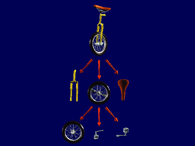
Java 3D is an object-oriented API. Applications construct individual graphics elements as separate objects and connect them together into a treelike structure called a scene graph. The application manipulates these objects using their predefined accessor, mutator, and node-linking methods.
Java 3D's scene graph-based programming model provides
a simple and flexible mechanism for representing and rendering scenes. The scene
graph contains a complete description of the entire scene, or virtual universe.
This includes the geometric data, the attribute information, and the viewing
information needed to render the scene from a particular point of view. Chapter
3, "Scene Graph Basics," provides more information on the Java 3D
scene graph programming model.
The Java 3D API improves on previous graphics APIs by eliminating many of the bookkeeping and programming chores that those APIs impose. Java 3D allows the programmer to think about geometric objects rather than about triangles-about the scene and its composition rather than about how to write the rendering code for efficiently displaying the scene.
Java 3D includes three different rendering modes: immediate mode, retained mode, and compiled-retained mode. Each successive rendering mode allows Java 3D more freedom in optimizing an application's execution. Most Java 3D applications will want to take advantage of the convenience and performance benefits that the retained and compiled-retained modes provide.
Immediate mode leaves little room for global optimization at the scene graph level. Even so, Java 3D has raised the level of abstraction and accelerates immediate mode rendering on a per-object basis. An application must provide a Java 3D draw method with a complete set of points, lines, or triangles, which are then rendered by the high-speed Java 3D renderer. Of course, the application can build these lists of points, lines, or triangles in any manner it chooses.
Retained mode requires an application to construct a scene graph and specify which elements of that scene graph may change during rendering. The scene graph describes the objects in the virtual universe, the arrangement of those objects, and how the application animates those objects.
Compiled-retained mode, like retained mode, requires the application to construct a scene graph and specify which elements of the scene graph may change during rendering. Additionally, the application can compile some or all of the subgraphs that make up a complete scene graph. Java 3D compiles these graphs into an internal format. The compiled representation of the scene graph may bear little resemblance to the original tree structure provided by the application, however, it is functionally equivalent. Compiled-retained mode provides the highest performance.
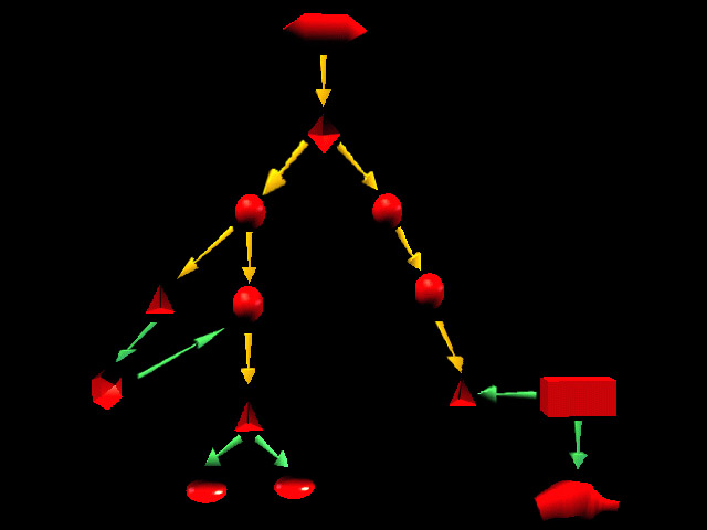
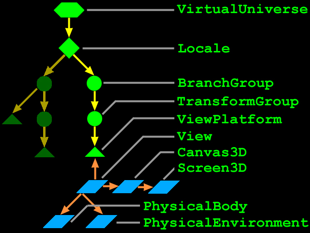
The scene graph consists of superstructure components-a VirtualUniverse object and a Locale object-and a set of branch graphs. Each branch graph is a subgraph that is rooted by a BranchGroup node that is attached to the superstructure.
The following steps are taken by the example program to create the scene graph elements and link them together. Java 3D will then render the scene graph and display the graphics in a window on the screen:
Most Java 3D programs build an identical set of superstructure
and view branch objects, so the Java 3D utility packages provide a universe
package for constructing and manipulating the objects in a view branch. The
classes in the universe package provide a quick means for building a single
view (single window) application. Listing 2-3 shows a code fragment for using
the SimpleUniverse class. Note that the SimpleUniverse constructor takes a Canvas3D
as an argument, in this case referred to by the variable myCanvas.
------------------------------------------------------------------------
   import com.sun.j3d.utils.universe.*;
   Shape3D myShape1 = new Shape3D(myGeometry1, myAppearance1);
   Shape3D myShape2 = new Shape3D(myGeometry2, myAppearance2);
   BranchGroup myBranch = new BranchGroup();
   myBranch.addChild(myShape1);
   myBranch.addChild(myShape2);
   myBranch.compile();
   SimpleUniverse myUniv = new SimpleUniverse(myCanvas);
   myUniv.addBranchGraph(myBranch);
while (true) {
   Process input
   if (exit request) break
   Check for collisions
   Perform behaviors
   Start playing appropriate sounds
   Traverse scene graph and render objects
}
Cleanup
View branch for viewing controls |
Content branch for 3D shapes, lights, etc. |
 |
 |
A VirtualUniverse object defines a named universe. Java 3D permits the creation of more than one universe, though the vast majority of applications will use just one. The VirtualUniverse object provides a grounding for scene graphs. All Java 3D scene graphs must connect to a VirtualUniverse object to be displayed.
JAVA 3D's superstructure consists of one or more VirtualUniverse objects, each of which contains a set of one or more high-resolution Locale objects. The Locale objects, in turn, contain collections of subgraphs that comprise the scene graph
The Virtual Universe
Java 3D defines the concept of a virtual universe as a
three-dimensional space with an associated set of objects. Virtual universes
serve as the largest unit of aggregate representation, and can also be thought
of as databases. Virtual universes can be very large, both in physical space
units and in content. Indeed, in most cases a single virtual universe will serve
an application's entire needs.
Virtual universes are separate entities in that no node object may exist in
more than one virtual universe at any one time. Likewise, the objects in one
virtual universe are not visible in, nor do they interact with objects in, any
other virtual universe.
To support large virtual universes, Java 3D introduces the concept of Locales
that have high-resolution coordinates as an origin. Think of high-resolution
coordinates as "tie-downs" that precisely anchor the locations of
objects specified using less precise floating-point coordinates that are within
the range of influence of the high-resolution coordinates.
A Locale, with its associated high-resolution coordinates, serves as the next
level of representation down from a virtual universe. All virtual universes
contain one or more high-resolution-coordinate Locales, and all other objects
are attached to a Locale. High-resolution coordinates act as an upper-level
translation-only transform node. For example, the coordinates of all objects
that are attached to a particular Locale are all relative to the location of
that Locale's high-resolution coordinates.
The Virtual Universe
While a virtual universe is similar to the traditional computer graphics concept
of a scene graph, a given virtual universe can become so large that it is often
better to think of a scene graph as the descendant of a high-resolution-coordinate
Locale.
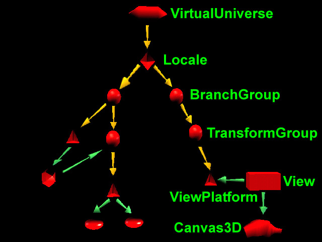
The right BranchGroup has a single subgraph that consists of a TransformGroup node and a ViewPlatform leaf node. The TransformGroup specifies the position (relative to the Locale), orientation, and scale of the ViewPlatform. This transformed ViewPlatform object defines the end user's view within the virtual universe.
Finally, the ViewPlatform is referenced by a View object that specifies all of the parameters needed to render the scene from the point of view of the ViewPlatform. Also referenced by the View object are other objects that contain information, such as the drawing canvas into which Java 3D renders, the screen that contains the canvas, and information about the physical environment.
Below the VirtualUniverse object is a Locale object. The Locale object defines the origin, in high-resolution coordinates, of its attached branch graphs. A virtual universe may contain as many Locales as needed. By default, a single Locale object is defined with its origin at (0.0, 0.0, 0.0).
A BranchGroup serves as the root of a subgraph, called a branch graph, of the scene graph. Only BranchGroup objects can attach to Locale objects.
public static void main( String[] args )
public classname( )
public static void main( String[] args )	{
   new MainFrame( new HelloUniverse( ), 640, 480 );
}
GraphicsConfigTemplate3D gcTemplate = new GraphicsConfigTemplate3D();
GraphicsEnvironment local = GraphicsEnvironment.getLocalGraphicsEnvironment();
// there could be more than one screen
GraphicsDevice screen = local.getDefaultScreenDevice();
GraphicsConfiguration configuration = screen.getBestConfiguration(gcTemplate);
// Get a Canvas3D and call its constructor with the configuration
mainCanvas3D = new Canvas3D(configuration);
// Add the canvas to a JPanel (which is part of a JFrame ...)
mainCanvas3D.setSize(200,200); // and / or
setLayout(new Border Layout)
add("Center", mainCanvas3D)
// The general Scene graph
VirtualUniverse myUniverse = new VirtualUniverse();
Locale myLocale = new Locale(myUniverse);
// Create the two main branches (with your functions)
BranchGroup myScene = myCreateSceneBranch();
BranchGroup myView = myCreateViewBranch(mainCanvas3D); // a canvas3D is needed
here !
// Add the two branches to the Locale ... AT THE END !!!
myLocale.addBranchGraph(myView);
myLocale.addBranchGraph(myScene);
/**
* This function builds the view branch of the scene
* graph.  It creates a branch group and then creates the
* necessary view elements to give a useful view of our
* content.
* @param c Canvas3D that will display the view
* @return BranchGroup that is the root of the view elements
*/
    protected BranchGroup myCreateViewBranch(Canvas3D c) {
        //This is the root of our view branch
        BranchGroup viewBranch = new BranchGroup();

        //The transform that will move our view
        //back 5 units along the z-axis
        Transform3D viewXfm = new Transform3D();
        viewXfm.set(new Vector3f(0.0f,0.0f,5.0f));

        //The transform group that will be the parent
        //of our view platform elements
        TransformGroup viewXfmGroup = new TransformGroup(viewXfm);
        viewTG.setCapability(TransformGroup.ALLOW_TRANSFORM_WRITE);

        // Deafult View and ViewPlateform
        ViewPlatform myViewPlatform = new ViewPlatform();
        View myView = new View();

        //Next the physical elements are created
        PhysicalBody myBody = new PhysicalBody();
        PhysicalEnvironment myEnvironment = new PhysicalEnvironment();

        //Then we put it all together
        myView.addCanvas3D(c);
        myView.setPhysicalBody(myBody);
        myView.setPhysicalEnvironment(myEnvironment);

        myView.attachViewPlatform(myViewPlatform);

        viewXfmGroup.addChild(myViewPlatform);
        viewBranch.addChild(viewXfmGroup);


        return viewBranch;
	}

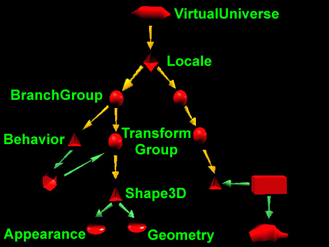
In this example there are two branch graphs and, thus,
two BranchGroup nodes. Attached to the left BranchGroup are two subgraphs. One
subgraph consists of a user-extended Behavior leaf node. The Behavior node contains
Java code for manipulating the transformation matrix associated with the object's
geometry.
The other subgraph in this BranchGroup consists of a TransformGroup node that
specifies the position (relative to the Locale), orientation, and scale of the
geometric objects in the virtual universe. A single child, a Shape3D leaf node,
refers to two component objects: a Geometry object and an Appearance object.
The Geometry object describes the geometric shape of a 3D object (a cube in
our simple example). The Appearance object describes the appearance of the geometry
(color, texture, material reflection characteristics, and so forth).
Optionally spawn threads