Modeling
Implicit Functions
the family of quadric surfaces
Or here is a sphere : (O,r)
Polygon Mesh
Parametric Cubic Curves and Bicubic Patches Using Splines
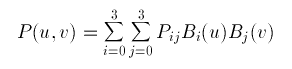
bicubic surface patches.
If one parameter is held at a constant value then the above will represent
a curve. Thus P(u,a) is a curve on the surface with the parameter v being a
constant a.
In a bicubic surface patch cubic polynomials are used to represent the edge
curves P(u,0), P(u,1), P(0,v) and P(1,v)as shown below. The surface is then
generated by sweeping all points on the boundary curve P(u,0) (say) through
cubic trajectories,defined using the parameter v, to the boundary curve P(u,1).
In this process the role of the parameters u and v can be reversed.
![]()
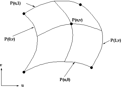
The representation of the bicubic surface patch can be
illustrated by considering the Bezier Surface Patch.
The edge P(0,v) of a Bezier patch is defined by giving four control points P00,
P01, P02 and P03. Similarly the opposite edge P(1,v) can be represented by a
Bezier curve with four control points. The surface patch is generated by sweeping
the curve P(0,v) through a cubic trajectory in the parameter u to P(1,v). To
define this trajectory we need four control points, hence the Bezier surface
patch requires a mesh of 4*4 control points as illustrated below.
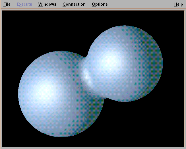
Metaballs
Metball modelling rests on the polygonization of an isosurface. The isosurface is defined as the set of all points in space where the force function is precisely equal to some chosen constant threshold.
The polygonization of the surface is a set of polygons which attempt to aproximate the form of the surface to the best of their resolution. The surface is not guaranteed to be accurate; shapes on the surface that fall below the resolution of the polygon mesh will not be represented accurately. But overall, polygonization is an effective way of displaying the isosurface, and so care must be taken to compute the polygon mesh as quickly and accurately as possible.
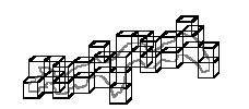
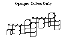
Surface-fitting Algorithms : How to draw isosurface
-
Contour Tracking
-
Opaque Cubes
-
Marching Cubes
-
Dividing Cubes
-
Marching Tetrahedra
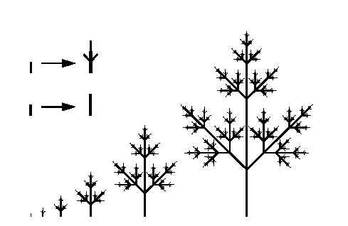
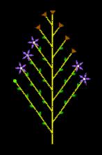
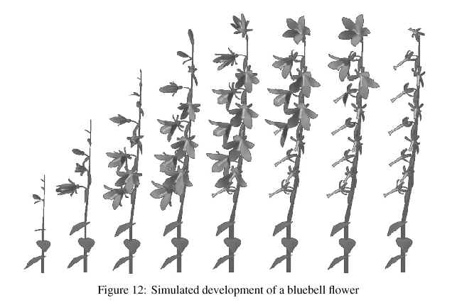
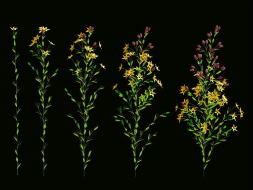
Procedural Modeling
Modeling Transformations
CSG
The method of Constructive Solid Geometry arose from the observation that many industrial components derive from combinations of various simple geometric shapes such as spheres, cones, cylinders and rectangular solids. In fact the whole design process often started with a simple block which might have simple shapes cut out of it, perhaps other shapes added on etc. in producing the final design. For example consider the simple solid below:
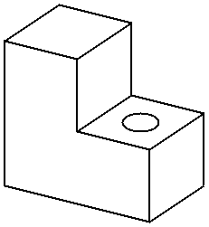
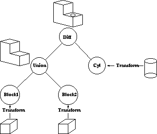
This simple component could be produced by gluing two rectangular blocks together and then drilling the hole. Or in CSG terms the the union of two blocks would be taken and then the difference of the resultant solid and a cylinder would be taken. In carrying out these operations the basic primitive objects, the blocks and the cylinder, would have to be scaled to the correct size, possibly oriented and then placed in the correct relative positions to each other before carrying out the logical operations.
The Boolean Set Operators used are:
- union - A + B is the set of points that are in A or B.
- intersection - A.B is the set of points that belong to A and B.
- difference - A-B is the set of points that belong to A but not to B.
Note that the above definitions are not rigorous and have to be refined to define the Regularised Boolean Set Operations to avoid impossible solids being generated.
A CSG model is then held as a tree structure whose terminal nodes are primitive objects together with an appropriate transformation and whose other nodes are Boolean Set Operations. This is illustrated below for the object above which is constructed using cube and cylinder primitives.
CSG methods are useful both as a method of representation and as a user interface technique. A user can be supplied with a set of primitive solids and can combine them interactively using the boolean set operators to produce more complex objects. Editing a CSG representation is also easy, for example changing the diameter of the hole in the example above is merely a case of changing the diameter of the cylinder.
However it is slow to produce a rendered image of a model from a CSG tree. This is because most rendering pipelines work on B-reps and the CSG representation has to be converted to this form before rendering. Hence some solid modellers use a B-rep but the user interface is based on the CSG representation.