|
|
NB. : in the lecture on Displays devices, we insisted on the particulate aspect of light (photon emission). But light is dual and today we will discuss about the waving side of light.
If you want to see all the colours, use a rainbow or a prism.
How do we perceive colour ?
Some white light, coming usually from the sun is absorbed and reflected on some surface, depending on the type of surface. We perceive the white light subtracted by the absorbed light.
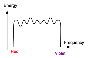
The white light is composed of a large span of wavelengths.
http://mo-www.harvard.edu/Java/MiniSpectroscopy.html
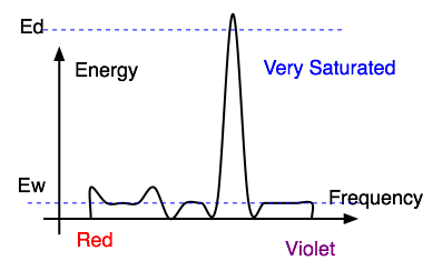
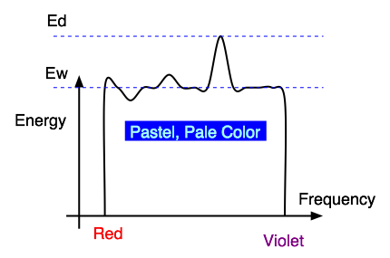
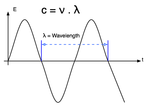
What we perceive as "light", or different colours, is a narrow frequency band within the electromagnetic spectrum.
c = n . l |
c = 3 x 1010 cm/s |

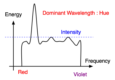
Ew : contribution of the other frequencies producing white lightEd : Energy density of the dominant light componentPurity of 100% when Ew = 0Purity of 0% when Ed = Ew |
|
The photosensitive part of the eye is called the retina.The retina is largely composed of two types of cells, called rods and cones. Only the cones are responsible for colour perception. |
 |
 |
Cones are most densely packed within a region of the eye called the fovea.There are three types of cones, referred to as S, M, and L. They are roughly equivalent to blue, green, and red sensors, respectively. Their peak sensitivities are located at approximately 430nm, 560nm, and 610nm for the "average" observer. |
 |
|
Colorblindness results from a deficiency of one or more cone type. Image : Peter K. Kaiser : http://www.yorku.ca/eye/recept3.htm Electron Micrograph of Human Visual Receptors |
|
|
 |
In order to define the perceptual 3D space in a "standard" way, a set of experiments have been carried by having observers try and match color of a given wavelength, lambda, by mixing three other pure wavelengths, such as R=700nm, G=546nm, and B=436nm in the following example.Note that the phosphours of color TVs and other CRTs do not emit pure red, green, or blue light of a single wavelength, as is the case for this experiment. |
 |
The scheme above can tell us what mix of R,G,B is needed to reproduce the perceptual
equivalent of any wavelength. A problem exists, however, because sometimes the
red light needs to be added to the target before a match can be achieved. This
is shown on the graph by having its intensity, R, take on a negative value.
Often it is convenient to work in a 2D color space.This is commonly done by projecting the 3D color space onto the plane X+Y+Z=1, yielding a CIE chromaticity diagram. The projection is defined as:
Giving one of the following chromaticity diagram. |
 |
 |
|
 |
 |
|
 |
 |
|
 |
The RGB space is a three-dimensional color space whose components are the red, green, and blue intensities that make up a given color. For example, scanners read the amounts of red, green, and blue light that are reflected from or transmitted through an image and then convert those amounts into digital values. Information displayed on a color monitor begins with digital values that are converted to analog signals for display on the monitor. The analog signals are transmitted to the phosphors on the face of the monitor, causing them to glow at various intensities of red, green, and blue (the combination of which makes up the required hue, saturation, and brightness of the desired colors).
RGB-based color spaces are the most commonly used color spaces in computer graphics, primarily because they are directly supported by most color displays and scanners. RGB color spaces are device dependent and additive. The groups of color spaces within the RGB base family include
Anycolor expressed in RGB space is some mixture of three primary colors: red, green, and blue. Most RGB-based color spaces can be visualized as a cube, as in the following figure, with corners of black, the three primaries (red, green, and blue), the three secondaries (cyan, magenta, and yellow), and white.

The sRGB color space is based on the ITU-R BT.709 standard. It specifies a gamma of 2.2 and a white point of 6500 degrees K. You can read more about sRGB space at the International Color Consortium site at http://www.color.org . This space gives a complimentary solution to the current strategies of color management systems, by offering an alternate, device-independent color definition that is easier to handle for device manufacturers and the consumer market. sRGB color space can be used if no other RGB profile is specified or available.
High end users with good quality reproduction devices may find that the sRGB space, which limits colors to the sRGB gamut, is too restrictive for their required color quality.
HSV space and HLS space are transformations of RGB space that can describe colors in terms more natural to an artist. The name HSV stands for hue, saturation, and value . ( HSB space , or hue , saturation , and brightness , is synonymous with HSV space.) HLS stands for hue, lightness, and saturation. The two spaces can be thought of as being single and double cones, as shown in next figure .
The components in HLS space are analogous, but not completely identical, to the components in HSV space:
HSV (or HSB) color space and HLS color space

are three variants of what is effectively the same colour space.
They all are effectively the RGB space twisted so that the neutral diagonal becomes the lightness axis, the saturation the distance from the central lightness axis and the hue the position around the center. The only difference between these models is the measurement of saturation, or the strength of the colour.
In HSV, created in 1978 by Alvey Ray Smith, saturation had a maximum on 0 when lightness was zero and 1 when lightness was 1. This is somewhat odd and anti-intuitive when the strength of the colour of white is considered. HLS is much more intuitive. The saturation peaks at a lightness of 0.5 and has a maximum of zero at black and white. The HSI colour space is in fact identical to HLS under a different name.
The most commonly used one, confusingly also called HSV, is a combination and variation on HSV and HLS, appearing to be a simple cylinder. This was done to have a uniform saturation limit. There are the same anomalies at white and black with saturation as with the original HSV. Whenever HSV is referred to in this report it will be to this colour space.
HSV is almost identical to RGB, slightly warped for symmetry's and simplicity's sake. It has made no attempts whatsoever towards perceptual uniformity but has achieved more intuitive dimensions.
Extract
from : Matthew A Seaborn : http://www.brunel.ac.uk/~eepgmas/report/node26.html
dye color |
absorbs |
reflects |
|---|---|---|
cyan |
red |
blue and green |
magenta |
green |
blue and red |
yellow |
blue |
red and green |
black |
all |
none |
To produce blue, one would mix cyan and magenta inks, as they both reflect blue while each absorbing one of green and red. Unfortunately, inks also interact in non-linear ways. This makes the process of converting a given monitor color to an equivalent printer color a challenging problem.
Black ink is used to ensure that a high quality black can always be printed, and is often referred to as to K. Printers thus use a CMYK color model.
 yields the color on monitor 2 which is equivalent to a given color on monitor
1. Conversion to-and-from printer gamuts is difficult. A first approximation
is as follows:
yields the color on monitor 2 which is equivalent to a given color on monitor
1. Conversion to-and-from printer gamuts is difficult. A first approximation
is as follows:
C = 1 - R
M = 1 - G
Y = 1 - B
K = min(C,M,Y) C' = C - K
M' = M - K
Y' = Y - K
 |
When we "compute" colors we generally assume that they are linear quanities. Unfortunately, most display devices are nonlinear. |
In the field of Computer Graphics, one often hears the phrase "gamma correction." What is this strange sounding thing and why does it matter to you?
Gamma correction matters if you have any interest in displaying an image accurately on a computer screen. Gamma correction controls the overall brightness of an image. Images which are not properly corrected can look either bleached out, or too dark. Trying to reproduce colors accurately also requires some knowledge of gamma. Varying the amount of gamma correction changes not only the brightness, but also the ratios of red to green to blue. (Example of this color phenomenon).Gamma correction also plays a big role in making images for the WWW.
To explain gamma correction we will begin with where you are looking - your computer monitor.
Almost every computer monitor, from whatever manufacturer, has one thing in common. They all have a intensity to voltage response curve which is roughly a 2.5 power function. Don't be afraid, this just means that if you send your computer monitor a message that a certain pixel should have intensity equal to x, it will actually display a pixel which has intensity equal to x ^ 2.5 Because the range of voltages sent to the monitor is between 0 and 1, this means that the intensity value displayed will be less than what you wanted it to be. (0.5 ^ 2.5 = 0.177 for example) Monitors, then, are said to have a gamma of 2.5
 Sample Input to Monitor  Graph of Input

 Output from Monitor      Graph of Output  L = V ^ 2.5
Note: The grayscale images will not look very good on 8-bit color computers. Also the gamma correction for these images is 1.0 so they were actually designed to be viewed on a system such as a Sun or a PC with no hardware correction. They may appear brighter on other systems. The important thing here is the relative difference that you see.
To correct this annoying little problem, the input signal to the monitor (the voltage) must be "gamma corrected".
The solution, fortunately, is a simple one. Since we know the relationship between the voltage sent to the monitor and the intensity which it produces, we can correct the signal before it gets to the monitor. The signal is adjusted so that it is essentially the complement of the curve shown above. There are other considerations as well when one speaks of a "correct" image. These include the ambient light in a room where the computer is, the brightness and contrast settings on the monitor, and finally personal taste.
Gamma Corrected Input
Graph of Correction L' = L ^ (1/2.5)
If gamma correction is done properly for the computer system, then the output should accurately reflect the image input.
Note that the task of gamma correction is accomplished by raising the input value to the 1/2.5 power. This is referred to as a gamma correction of 2.5. because we are correcting the input for a monitor whose gamma is 2.5
As we mentioned above, most monitors work in about the same way with respect to gamma correction. Most computers, or more specifically, most computer systems, do not work in exactly the same way, however.
By computer systems we mean everything from the software that is running (like Netscape) to the graphics cards installed, to the standard hardware on the motherboard. Different computers do different things and many "systems" have different configurations of all of the above things.
Macintoshes, for example, have partial gamma correction built-in to their hardware. Silicon Graphics computers also have built-in gamma correction, but it is different from the Macintosh. Suns and PCs have no standard built-in gamma correction but some graphics cards installed in these computers may provide this functionality.
Macintosh
The Macintosh has built-in gamma correction of 1.4. This means that after the software sends the signal to the framebuffer, there are internal hardware corrections which will further process the signal, specifically by gamma correcting it another 1.4 - That is, the signal is raised to the 1/1.4. Therefore, to get full correction, the software itself should first adjust the signal by raising it to the 1/1.8 power. (2.5/1.4 = 1.8) Thus the system gamma on a Macintosh is 1.8.SGINote some graphics cards in Macintoshes may have their own software to change the standard gamma and Adobe Photoshop 3.0 is now released with a gamma control panel from Knoll software which allows the user to change the system gamma of their Macintosh. The 1.8 standard is still accepted as the universal Mac System Gamma, but users should be aware that a Mac can be set differently. The Knoll software control panel for the Mac rewrites the look up table, (LUT) with a value of g/2.5 where g is the gamma the user selects. Thus selecting 1.8 will rewrite the LUT with 1.8/2.5 = 1/1.4 - the default setting. (The values in the LUT are 1/1.4 and this is called a 1.4 correction)
The SGI is similar to the Macintosh but instead of a hardware correction of 1.4 the SGI applies gamma correction of 1.7. Thus the system gamma for an SGI is 2.5/1.7 or roughly 1.5. Sometimes you may see that an SGI has a system gamma of 1.4. This calculation is made on the assumption that monitors have a response curve closer to a 2.4 power function.Suns and PCsSGI's also come with a utility to rewrite the internal hardware correction. These values are stored in a look up table, (LUT) and can be altered. The default is 1/1.7 as mentioned above. (The values in the table are 1/1.7, so we call this a 1.7 correction) Sometimes the value in the LUT may be referred to as the SGI system gamma. This is not the definition used on other platforms. Unlike the Mac gamma control panel, the SGI gamma utility will rewrite the LUT with the actual value set by the user.
Suns and PCs have no standard hardware correction (although certain graphics cards for these platforms may) and therefore their system gammas are roughly 2.5. (More about Sun's SX hardware and gamma)
Common graphics software such as Adobe Photoshop allows
the user to set the gamma correction value they want. (In Photoshop it is found
in Monitor Setup under Preferences under the File Menu.)
Extract from : CGSD - Gamma Correction Explained : http://www.cgsd.com/papers/gamma_intro.html
Extract from : CGSD - Gamma Correction Explained : http://www.cgsd.com/papers/gamma_diagram.html
Note: This diagram will not look very good in 8-bit color and your browser must support tables for the correct layout.
This diagram shows the cumulative effect of each of the gamma steps
| Input Signal | Software Correction Required | Built In Hardware Correction | Output Signal | |||||
|---|---|---|---|---|---|---|---|---|
| Sun & PC no Correction |
|
|
. | . | . | . | |
|
| Sun & PC full Software Correction |
|
|
|
|
. | . | |
|
| Macintosh Hardware Correction Only |
|
|
. | . |  |
 |
 |

|
| Macintosh Hardware and Software Correction |
|
| 
| 
|
|
|
|
|
| SGI Hardware Correction Only |
|
| . | . | 
| 
| 
| 
|
| SGI Hardware and Software Correction |
|
|
|
|
|
|
|
|
The table above shows the effects of various gamma corrections for a sample input. The sample input is a linear greyscale which was first made in Lab color space in Adobe Photoshop. The input is changed by software gamma correction, hardware gamma correction and, at the far right, by the the CRT display. This document assumes that the CRT has a luminance to input voltage response curve which matches a 2.5 power function.
The Software Correction Required column shows what level of gamma correction should be applied in software on the various platforms to achieve the correct output signal. In this case, the correct output means that it exactly matches the input signal - the linear greyscale.
The Built-In Hardware Correction column refers to the gamma correction done by the hardware on each platform. It is stated that Suns and PC's (Intel Standard) have no built-in hardware correction. This is the standard for these platforms, but certain graphics cards on each platform may perform some gamma correction.
The Output Signal column refers to the luminance to input voltage response curve as described above.
Note: The greyscale images shown above could themselves require gamma correction for display on your monitor. They were design to be viewed on a system that does no gamma correction in its hardware (such as a Sun or a PC) If you are viewing these images on a Macintosh or an SGI or have some other system (including Sun and PC) configured differently, they will appear a little too light (bleached out). Their purpose is mostly to illustrate what happens in the various steps relative to each other, and not as absolute representations of what you will on each system when viewed from your system. The only solution to this would be for us to put up many different copies corrected for different gamma settings and ask you which one you want to view.
Gamma does not affect the representation of a color in all color spaces equally and has no affect on color representation in many color spaces. (A color is represented in a "color space" as a set of coordinates (R,G,B = 255,255,255) for example. The are many different color spaces commonly used. Each is a 3 or 4 dimensional coordinate system used to express color information.)
Below are two lists of color spaces. The colors listed as device dependent are functions of the "system gamma" used. The colors spaces listed as device independent are not a function of gamma at all.
The greatest effect of Gamma on the representations of these colors is a change in overall brightness.
To see this visually using Adobe Photoshop, change the Gamma setting in the Monitor Setup (File Menu -> Preferences -> Monitor Setup). An image in RGB space should become lighter as you raise the gamma setting and darker as you decrease the gamma setting. An image in Lab space (Photoshop calls this Lab Mode) should not be affected by gamma. Some earlier versions of Photoshop may not support Lab color space.
A change in gamma can also effect hue of a particular color representation.
For example, the color below, represented in RGB space has 80% Red, 20% Green
and 20% Blue, or 8:2:2 ratio.


One say the gamma correction is simulated, because your browser has no notion of gamma correction and therefore One can't tell it that these two colors need different gamma correction. Even if your browser did no about gamma, and know what to do with it, the JPEG and GIF formats do not store gamma. The colors were made in Adobe Photoshop in Lab color space and converted to RGB space using the gamma mentioned.
            Gamma Correction = 1.0         Gamma Correction = 2.5
          Source           Output         Source             Output
           R 80%            R  57%         R 80%              R 80%
           G 20%            G  ~0%         G 20%              G 20%
           B 20%            B  ~0%         B 20%              B 20%
Extract from : CGSD - Gamma Correction Explained
: http://www.cgsd.com/papers/gamma_intro.html
Computer memory is traditionally organized in bytes, which are units of 8 consecutive bits. The string "Hello" would typically occupy 6 consecutive byte addresses in memory, represented schematically as follows:
0x00329384 'H'
0x00329385 'e'
0x00329386 'l'
0x00329387 'l'
0x00329388 'o'
0x00329389 '0'
The (hexadecimal) address of each memory location is shown at the left, and the value in that location is shown at the right. Note that the end of the string is indicated by a null character ('0') in some languages, such as C and C++. Other languages may use different conventions.
In C and C++, this could be indicated by the data type "short" or "unsigned short", or in Java by "short". For definiteness, suppose this integer has the value 12, which is "0x000c" in hexadecimal. If this were stored at the same address as the 'H' in the word "Hello", how would it look?
0x00329384 '00'
0x00329385 '0c'
because the most significant byte of the word is stored first (at lower address). Most computer chips use this convention.
0x00329384 '0c'
0x00329385 '00'
for the obvious reason. Intel uses this convention, I suppose just to be different.
Suppose you read a binary file written on a big-endian computer system using a little-endian system? You will get all the values wrong unless you exchange the order of the bytes. In such a case, you care!
The Color class is used encapsulate colors in the default
sRGB color space or colors in arbitrary color spaces identified by a ColorSpace.
Every color has an implicit alpha value of 1.0 or an explicit one provided in
the constructor. The alpha value defines the transparency of a color and can
be represented by a float value in the range 0.0 - 1.0 or 0 - 255.
An alpha value of 1.0 or 255 means that the color is completely opaque and an
alpha value of 0 or 0.0 means that the color is completely transparent. When
constructing a Color with an explicit alpha or getting the color/alpha components
of a Color, the color components are never premultiplied by the alpha component.
The default color space for the Java 2D(tm) API is sRGB, a proposed standard
RGB color space.
http://www.w3.org/Graphics/Color/sRGB.html
An implementation of the abstract ColorSpace class. This representation of device independent and device dependent color spaces is based on the International Color Consortium Specification ICC.1:1998-09