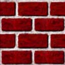
Texture Image : 128 x 128
|
Texture Image : 128 x 128 |
|
Select a texture image and control basic mapping attributes
Control advanced mapping attributes
Automatically generate texture coordinates if you do not provide your own (most people provide their own)
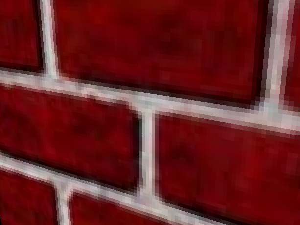
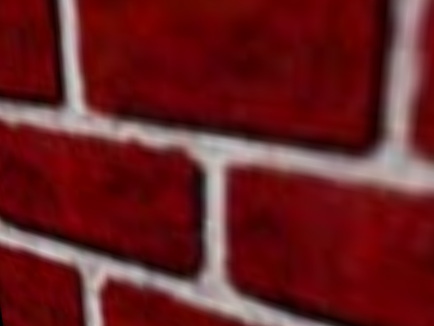
TextureLoader myLoader = new TextureLoader( "brick.jpg",
this );
ImageComponent2D myImage = myLoader.getImage( );
Toolkit tk = Toolkit.getDefaultToolkit();

img = tk.getImage("AnyImage.gif");

try {
	MediaTracker tracker = new MediaTracker(this);
	tracker.addImage(img, 0);
	tracker.waitForID(0);
	}
catch ( Exception e ) {}

ImageComponent2D image =
	new ImageComponent2D(ImageComponent2D.FORMAT_RGB, img);
Texture2D myTex = new Texture2D( );
myTex.setImage( 0, myImage );
myTex.setEnable( true );
Appearance myAppear = new Appearance( );
myAppear.setTexture( myTex );
Shape3D myShape = new Shape3D( myText, myAppear );
The TextureLoader utility loads an image from a file or URL, and returns an ImageComponent or Texture
Must be powers of 2
Like the Alpha of Animations
Creating and editing texture images is something that
is normally done external to Java 3D programs. In fact, most texture images
are prepared before the program is begun. There are two essential tasks in texture
image preparation:
1. ensuring the images are of acceptable dimensions, and
2. ensuring the images are saved in a file format which can be read.
Of course the image could be edited to achieve the desired color, transparency, and tiling characteristics.
For rendering efficiency, Java 3D requires the size of the texture image to be a mathematical power of two (1, 2, 4, 8, 16, �) in each dimension. Failing to meet this restriction will result in a runtime exception. If an image is not of acceptable dimensions, it must be modified (scaled or cropped) to meet the dimension requirements before it is used.
Image editing can be done in a wide variety of programs including the Java Advanced Imaging API 2 . In Figure, the two smaller images are 128 by 128, the tree is 256 by 128, and the earth is 256 by 256.
As far as the file formats are concerned, any file format can be used provided there is a method to load it.
void setTextureCoordinates( int index, * texCoord )
void setTextureCoordinateIndices( int index, int[] value )
TextureLoader myLoader = new TextureLoader( "brick.jpg",
this );
ImageComponent2D myImage = myLoader.getImage( );
Toolkit tk = Toolkit.getDefaultToolkit();

img = tk.getImage("AnyImage.gif");

try {
	MediaTracker tracker = new MediaTracker(this);
	tracker.addImage(img, 0);
	tracker.waitForID(0);
	}
catch ( Exception e ) {}

ImageComponent2D image =
	new ImageComponent2D(ImageComponent2D.FORMAT_RGB, img);
Texture2D myTex = new Texture2D( );
myTex.setImage( 0, myImage );
myTex.setEnable( true );
Appearance myAppear = new Appearance( );
myAppear.setTexture( myTex );
Shape3D myShape = new Shape3D( myText, myAppear );
/**
* This defines the appearance with a texture.
* The texture is loaded from an external file.
* @return Appearance that uses the texture.
*/
protected Appearance DefineAppearance() {
//Load the texture from the external image file
TextureLoader textLoad = new TextureLoader("housebrick.jpg", this);
//Access the image from the loaded texture
ImageComponent2D textImage = textLoad.getImage();
//Create a two dimensional texture
Texture2D texture = new Texture2D(Texture2D.BASE_LEVEL, Texture.RGB,
textImage.getWidth(), textImage.getHeight());
//Set the texture from the image loaded
texture.setImage(0, textImage);
//Create the appearance that will use the texture
Appearance app = new Appearance();
app.setTexture(texture);
//Define how the texture will be mapped onto the surface
//by creating the appropriate texture attributes
TextureAttributes textAttr = new TextureAttributes();
textAttr.setTextureMode(TextureAttributes.REPLACE);
app.setTextureAttributes(textAttr);
app.setMaterial(new Material());
return app;
}
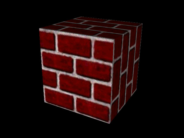
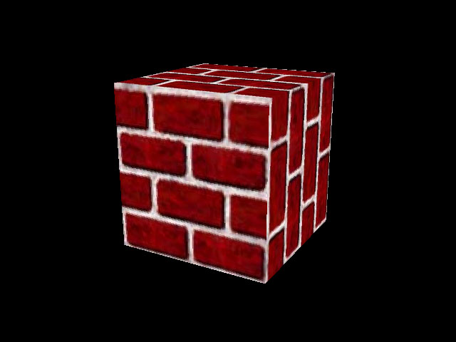
/**
* Build a cube from an IndexedQuadArray. This method creates
* the vertices as a set of eight points and the normals as a set of
* six vectors (one for each face). The data is then defined such
* that each vertex has a different normal associated with it when
* it is being used for a different face. The shape is created with
* texture coordinates so that when the appearance is set it will
* use the appearance texture on the surface.
* @return Node that is the shape.
*/
protected Node buildShape() {
IndexedQuadArray indexedCube = new IndexedQuadArray(8,
IndexedQuadArray.COORDINATES|
IndexedQuadArray.NORMALS|
IndexedQuadArray.TEXTURE_COORDINATE_2, 24);
Point3f[] cubeCoordinates = { new Point3f( 1.0f, 1.0f, 1.0f),
new Point3f(-1.0f, 1.0f, 1.0f),
new Point3f(-1.0f,-1.0f, 1.0f),
new Point3f( 1.0f,-1.0f, 1.0f),
new Point3f( 1.0f, 1.0f,-1.0f),
new Point3f(-1.0f, 1.0f,-1.0f),
new Point3f(-1.0f,-1.0f,-1.0f),
new Point3f( 1.0f,-1.0f,-1.0f)};
Vector3f[] normals= {new Vector3f( 0.0f, 0.0f, 1.0f),
new Vector3f( 0.0f, 0.0f,-1.0f),
new Vector3f( 1.0f, 0.0f, 0.0f),
new Vector3f(-1.0f, 0.0f, 0.0f),
new Vector3f( 0.0f, 1.0f, 0.0f),
new Vector3f( 0.0f,-1.0f, 0.0f)};
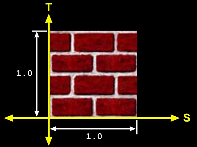
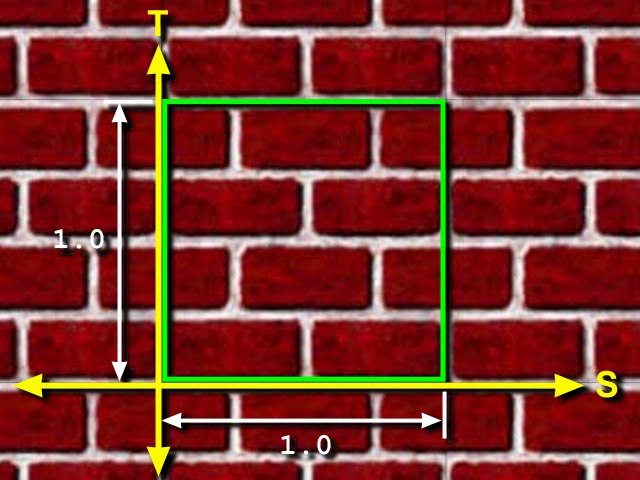
//Define the texture coordinates. These are defined
//as floating point pairs of values that are used to
//map the corners of the texture image onto the vertices
//of the face. We then define the indices into this
//array of values in a similar way to that used for
//the vertices and normals.
TexCoord2f[] textCoord = { new TexCoord2f(1.0f,1.0f),
new TexCoord2f(0.0f,1.0f),
new TexCoord2f(0.0f,0.0f),
new TexCoord2f(1.0f,0.0f)};
int coordIndices[] = {0,1,2,3,7,6,5,4,0,3,7,4,5,6,2,1,0,4,5,1,6,7,3,2};
int normalIndices[] = {0,0,0,0,1,1,1,1,2,2,2,2,3,3,3,3,4,4,4,4,5,5,5,5};
int textIndices[] = {0,1,2,3,3,0,1,2,1,2,3,0,1,2,3,0,3,0,1,2,1,2,3,0};
indexedCube.setCoordinates(0, cubeCoordinates);
indexedCube.setCoordinateIndices(0, coordIndices);
indexedCube.setNormals(0,normals);
indexedCube.setNormalIndices(0, normalIndices);
indexedCube.setTextureCoordinates(0,0,textCoord);
indexedCube.setTextureCoordinateIndices(0,0,textIndices);
return new Shape3D(indexedCube, DefineAppearance());
}
TextureAttributes myTA = new TextureAttributes( );
Transform3D myTrans = new Transform3D( );
myTrans.rotZ( Math.PI/4.0 ); // 45 degrees
myTA.setTextureTransform( myTrans );
Appearance myAppear = new Appearance( );
myAppear.setTextureAttributes( myTA );
Shape3D myShape = new Shape3D( myText, myAppear );
This setting simply specifies if the texture coordinates will be generated for a two or three dimensional texture. The possible settings are TEXTURE_COORDINATE_2 and TEXTURE_COORDINATE_3 which generates 2D texture coordinates (S and T) and 3D texture coordinates (S, T, and R), respectively.
There are two basic texture generation approaches: linear projection or sphere mapping.
With linear projection, the texture coordinates are specified
with planes. For texture coordinates of two dimensions (s,t), two planes are
used. The distance from a vertex to one plane is the texture coordinate in one
dimension; distance to the other plane to a vertex is the texture coordinate
in the other dimension. For three dimensional textures, three planes are used.
The three possible plane parameters are named planeS, planeT, and planeR, where
the name corresponds to the dimension for which it is used.
Each plane is specified as a 4-tuple (plane equation). The first three values
are the surface normal vector for the plane. The fourth value specifies the
distance from the origin to the plane along a vector parallel to the plane's
surface normal vector.
There are two variations on this automatic texture coordinate generation method. The first, called object linear, produces static texture coordinates. With object linear generated texture coordinates, if the visual object moves, the texture coordinates do not change. The second option, called eye linear, produces texture coordinates relative to the eye coordinates resulting in variable texture coordinates for the object. With eye linear texture coordinates moving objects appear to move through the texture.
DEMO Texture Generation
subdirectory of the examples jar distributed with this tutorial. This is one application you should run to see the difference. The example program is written with the Generation Mode set to EYE_LINEAR. Line 100 is the place to change to OBJECT_LINEAR generation mode.
If a shiny object is in the middle of a real room, the shiny object would likely reflect the image of many of the other objects in the room. The reflections would depend on the shape of the object and orientation of things in the room. The sphere map coordinate generation mode is designed to assign texture coordinates to approximate the reflections of other objects onto the visual object as would happen for the shiny object in the example real world. When a TexCoordGeneration object is used in sphere map generation mode the texture coordinates are calculated based on the surface normals and the viewing direction. The texture used for this effect must be specially prepared. If the virtual environment of the shiny object exists in the real world, a photograph of the scene taken with a fisheye lens will create a suitable texture image. If the scene does not exist, then the texture must be created to look like the image is a photograph taken with a fisheye lens.
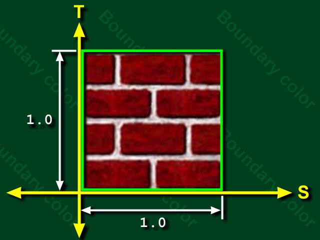
void setBoundaryModeS( int mode )
void setBoundaryModeT( int mode )
void setBoundaryColor( Color4f color )
| REPLACE |
Texture color completely replaces the shape's material color |
| DECAL |
Texture color is blended as a decal on top of the shape's material color |
| MODULATE |
Texture color modulates (filters) the shape's material color |
| BLEND |
Texture color blends the shape's material color with an arbitrary blend color |
Mode |
Result color |
Result transparency |
|---|---|---|
REPLACE |
Trgb |
Ta |
DECAL |
Srgb*(1-Ta)+Trgb*Ta |
Sa |
MODULATE |
Srgb*Trgb |
Sa*Ta |
BLEND |
Srgb*(1-Trgb)+Brgb*Trgb |
Sa*Ta |
 |
|
| REPLACE | DECAL |
|---|---|
 |
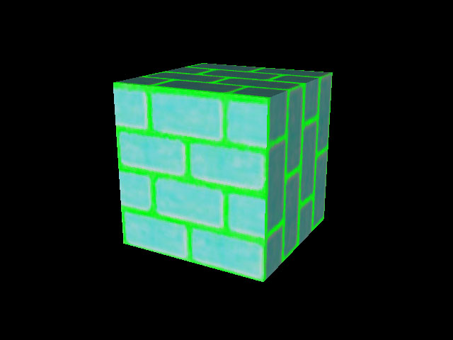 |
| MODULATE with white | BLEND with green |
 |
 |
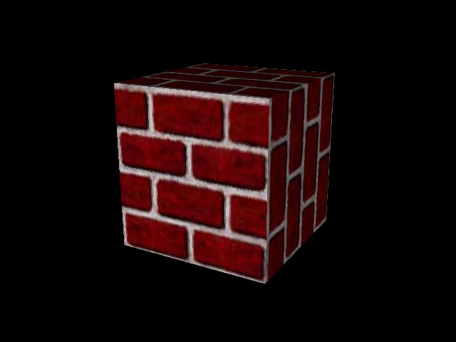
BASE_LEVEL_POINT
|
BASE_LEVEL_LINEAR
|